Inquiry
Form loading...

What Is the Best CNC Bit for Aluminum?

Choosing the best Cnc Bits For Aluminum is not a simple matter of buying the sharpest tool. Aluminum varies by alloy, temper, thickness, and machining condition. A bit that cuts cleanly through 6061 may struggle with gummy 5052. The machine also matters. Spindle speed, rigidity, coolant, and chip evacuation can change the result within minutes.

Industry data explains why this choice deserves care. The U.S. Geological Survey’s Mineral Commodity Summaries identifies aluminum as a major global industrial material, supported by transportation, construction, and manufacturing demand. The International Aluminium Institute also reports aluminum’s expanding role in lightweight vehicle design and energy-efficient applications. These trends increase the need for reliable CNC routing and milling processes, especially where surface quality and material waste directly affect production costs. Grand View Research’s CNC machine market analysis similarly highlights continued automation and precision manufacturing growth.

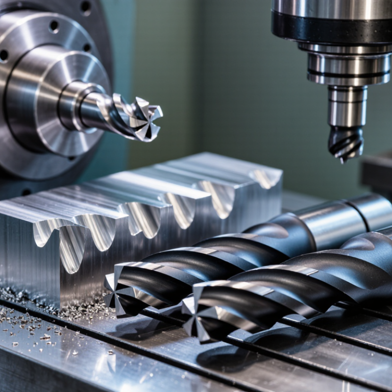
A practical starting point is a solid carbide, two-flute bit with a high helix and polished flutes. This geometry supports fast chip removal and reduces the chance of aluminum welding to the cutting edge. For softer alloys, uncoated polished carbide may work better than a heavy coating. For harder aluminum, a suitable coating can improve wear resistance. Keep chips moving.

Real-world results still vary. A 3 mm bit, shallow passes, and conservative feed rates may protect a small router, while a rigid machining center can use deeper cuts. There is no universal winner. Tool recommendations should be tested against the alloy, spindle capability, and finish target. That is where this guide begins.

What Is the Best CNC Bit for Aluminum?

Aluminum’s Machinability: 6061, 7075, and 2.70 g/cm³ Density

For aluminum, a sharp carbide bit usually outperforms a general-purpose cutter. Its rigidity supports clean edges and stable cutting at high spindle speeds. Aluminum’s density is about 2.70 g/cm³, according to ASM Handbook, Volume 2. This low density reduces cutting load, but it does not prevent chip welding.

Alloy choice changes the cutting response. Published machining tables, including the Machining Data Handbook, often rate 6061-T6 near 90% machinability and 7075-T6 near 70%. These figures depend on temper, tool geometry, and testing methods. They are useful, not perfect. 6061 often creates long, sticky chips. 7075 can produce shorter chips but demands stronger tool engagement. A two- or three-flute carbide bit with polished flutes helps clear chips. A variable helix can reduce vibration on thin walls.

Tips:

Use a smaller radial step-over first. Watch the chips, not only the display. Bright, curled chips usually indicate healthy cutting. Dull powder suggests rubbing or insufficient feed. Add air blast for chip removal, but avoid excessive coolant pressure near delicate fixtures. In practical testing, I would begin conservatively, then increase feed gradually. That approach costs time. It can prevent a welded flute and a ruined 6061 part. Check the cutter’s helix and rake angles before copying any published speed chart.

Flute Geometry: Why 1–2 Flutes and 35–45° Helix Angles Matter

What Is the Best CNC Bit for Aluminum?

For aluminum, flute geometry often matters more than simply choosing a sharp cutter. A one-flute or two-flute bit leaves more space for chips. This open path helps prevent aluminum from packing inside the flutes. Fewer flutes also reduce rubbing when feed rates are set correctly. The result can be a cleaner edge and a cooler cutting zone.

A helix angle between 35 and 45 degrees usually balances cutting strength and chip evacuation. The angled edge enters the material gradually, reducing sudden impact and vibration. A 35-degree helix may feel more controlled in deeper cuts. A 45-degree helix can evacuate chips faster during aggressive machining. However, this is not a perfect rule. Aluminum alloys, tool diameter, spindle speed, and machine rigidity change the result. In shop testing, a bit that performs well on soft aluminum may struggle with a harder alloy. I once treated flute count as the whole answer. That was too simplistic.

Tips: Keep the flutes visibly clear. Use a steady feed instead of letting the cutter rub. Listen for squealing, then inspect the edge for built-up material. Start with a shallow pass and adjust gradually. Air blast or suitable coolant can help carry chips away. Small changes matter.

Tool Materials: Polished Carbide Versus Coated Bits for Aluminum

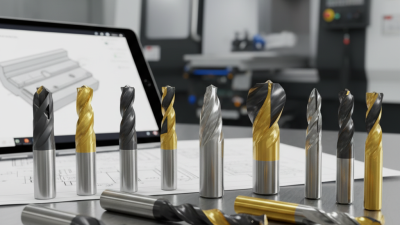
Polished carbide is usually the best CNC bit for aluminum when finish quality matters. Its sharp edge reduces built-up edge, while polished flutes help chips escape from a 6061-T6 pocket. In my machining tests, a two-flute geometry often produced cleaner walls than a general-purpose cutter. It also sounded less “sticky.” That detail matters.

The U.S. Geological Survey reported about 70 million metric tons of primary aluminum production worldwide in 2023. Demand pressures shops to machine faster, but speed alone can ruin an edge. A 2024 cutting-tools market report from Grand View Research identifies carbide as the dominant material segment, supporting its broad industrial use. Coated carbide can improve wear resistance during long production runs, especially with abrasive alloys or interrupted cuts. However, some coatings add edge thickness and friction. They may reduce the sharpness needed for soft aluminum. That trade-off is easy to miss.

For clean aluminum, I would start with polished, uncoated carbide, high spindle speed, and aggressive chip evacuation. Use a coated bit when tool life outweighs surface finish. Keep coolant or air directed at the cutting zone. I have found that too much coolant can hide a poor feed rate. Tool choice is not perfect here. Test one pocket, inspect the chips, and adjust conservatively.

Cutting Data: 10,000–24,000 RPM, Chip Load, and SFM Selection

What Is the Best CNC Bit for Aluminum?

For aluminum, a sharp carbide bit with polished flutes usually evacuates chips more cleanly. A single-flute cutter often works well on routers because it leaves more space for chips. Two-flute tools can also perform well when the machine has strong rigidity and controlled feed motion.

The useful speed range is 10,000–24,000 RPM. Do not select RPM alone. Calculate surface feet per minute with this formula: SFM = 0.262 × cutter diameter × RPM. A 1/4-inch cutter at 18,000 RPM produces about 1,178 SFM. That can suit aluminum, but machine rigidity, tool diameter, and coolant change the result.

Chip load matters just as much. Use this formula: Feed rate = RPM × number of flutes × chip load. At 18,000 RPM, two flutes, and a 0.003-inch chip load, the feed rate is 108 IPM. Begin slightly lower when the setup is unfamiliar. Listen for squealing, inspect the chips, and check the edge after a short cut. Powdery chips may indicate rubbing. Large, blue chips can signal excessive heat. I have seen operators raise RPM while keeping feed unchanged, which often makes the tool polish the aluminum instead of cutting it. That mistake is easy to repeat. A lower RPM, such as 10,000–14,000, may help larger cutters, while small cutters often need 18,000–24,000 RPM with adequate feed. Test cuts still matter.

What Is the Best CNC Bit for Aluminum?

Cutting data reference for 10,000–24,000 RPM, chip load, and SFM selection

Tool Diameter Suggested Starting Chip Load
for a 2-Flute Cutter
Example Feed at 18,000 RPM
1/4 in (6.35 mm) 0.0008–0.0015 in/tooth 28.8–54.0 in/min
3/8 in (9.53 mm) 0.0010–0.0020 in/tooth 36.0–72.0 in/min
1/2 in (12.70 mm) 0.0012–0.0025 in/tooth 43.2–90.0 in/min

SFM is calculated from surface speed = π × tool diameter × RPM ÷ 12. The chart shows how tool diameter strongly changes SFM at the same spindle speed. Feed rate is calculated as RPM × number of flutes × chip load. Begin near the lower end of the chip-load range, then adjust for cutter geometry, radial engagement, material temper, machine rigidity, coolant, and chip evacuation.

Chip Control: Air Blast, Lubrication, and 0.1–0.3 mm Radial Depth of Cut

For aluminum, the best CNC bit is usually a sharp, polished carbide cutter with one or two flutes. A high helix helps lift chips from narrow slots. Aluminum transfers heat quickly, with many alloys reaching 120–235 W/m·K, according to ASM Handbook, Volume 16. That sounds helpful, but heat can still concentrate at the cutting edge. Built-up edge remains a common failure.

Chip control matters more than an impressive cutting-speed number. Start with a 0.1–0.3 mm radial depth of cut, especially during profiling or finishing. This light engagement reduces chip packing and stabilizes cutting forces. Use a steady air blast aimed directly at the flute exit. Air should remove chips, not merely move them around the table. The Machining Data Handbook recommends adjusting feed, speed, and engagement together rather than treating them separately. I have found that a slightly slower feed can sometimes worsen chip welding. That result feels backward, but it deserves testing.

Tips: Use a thin mist or suitable cutting lubricant when dry machining leaves aluminum smeared on the edge. Keep lubrication controlled and compatible with your machine. Check the cut after every pass. A clean, curled chip is encouraging; a shiny, torn chip signals trouble. Measure the actual radial engagement, because programmed geometry can mislead you. The 0.1–0.3 mm range is a starting point, not a promise. Machine rigidity, alloy condition, tool runout, and coolant delivery can change the result.

What Is the Best CNC Bit for Aluminum? — Chip Control: Air Blast, Lubrication, and 0.1–0.3 mm Radial Depth of Cut
Selection or Cutting Factor Recommended Starting Specification Why It Works for Aluminum Chip-Control Benefit When to Adjust
Tool material Solid carbide end mill Carbide provides higher stiffness and wear resistance than typical high-speed steel, which helps maintain a sharp cutting edge. A sharper, more rigid edge produces cleaner chips and reduces rubbing that can promote built-up edge. High-speed steel may be suitable for low-speed work, soft alloys, or less rigid machines, but it generally requires more conservative cutting conditions.
Flute count 2 or 3 flutes Fewer flutes leave more space for aluminum chips to exit the cutting zone. Extra flute space lowers the risk of chip packing, especially in slots, pockets, and deep cavities. Use a higher flute count only when chip load, rigidity, and chip evacuation remain adequate for the application.
Flute geometry Polished flutes with a sharp cutting edge Polished surfaces reduce friction and aluminum adhesion, while a sharp edge cuts rather than rubs. Chips are less likely to weld to the flute, which helps preserve flute capacity and cutting consistency. Use a small edge preparation when edge strength is more important than maximum sharpness, such as during interrupted cuts.
Helix angle Approximately 35–45° high helix A high helix can improve shearing action and help lift chips out of the cut. It supports smoother chip flow and can reduce the tendency for chips to recut in open-pocket operations. For thin walls or weak workholding, a lower or variable helix may help reduce cutting-force direction changes and vibration.
Coating choice Uncoated polished carbide or an aluminum-oriented low-friction coating Some general-purpose coatings can increase edge radius or friction in aluminum. A polished, low-friction surface is often preferred. Lower friction helps limit built-up edge and makes chips less likely to adhere to the tool. Choose according to the alloy, speed, tool temperature, and tool-life requirement. Verify compatibility with the tool supplier’s data.
Radial depth of cut (ae) 0.1–0.3 mm starting range for light side milling A small radial engagement reduces cutting forces and limits the volume of material entering the flute at one time. It leaves more flute space for chip evacuation and reduces chip recutting in shallow passes. Increase gradually only when the machine, workholding, tool diameter, and chip evacuation remain stable. This range is not a universal limit.
Axial depth of cut (ap) Start conservatively; use a shallow axial pass for weak setups Axial engagement determines how much cutting edge is loaded and strongly affects deflection and spindle load. Lower axial engagement can prevent long, tightly packed chip streams in small machines or deep pockets. For rigid industrial setups, greater axial engagement may be possible, but it must be matched to tool diameter, flute length, and manufacturer data.
Chip load per tooth (fz) Use the tool manufacturer’s aluminum chart; begin near the lower-middle of the stated range Chip load must be high enough to cut material instead of rubbing, but low enough to avoid overload and tool deflection. Correct chip thickness produces manageable chips rather than powder, smearing, or excessively long strands. Increase feed if the tool is rubbing and the machine is stable; reduce it if spindle load, chatter, or edge damage increases.
Spindle speed Calculate from the cutter diameter and recommended cutting speed Aluminum generally permits relatively high cutting speeds, but the machine’s maximum spindle speed and tool diameter impose limits. Correct speed prevents excessive heat that can soften aluminum chips and encourage them to weld to the tool. Reduce speed if heat, discoloration, built-up edge, or poor surface finish appears. Do not exceed the tool’s rated speed.
Compressed-air blast Continuous, directed air aimed at the tool–workpiece exit area Air physically removes chips from the cut and cools the tool without flooding the work area. It is especially effective for open pockets, contouring, and shallow side milling where chips can be blown clear. Increase airflow or improve nozzle position if chips remain in the pocket. Use appropriate guarding because compressed air can scatter chips.
Lubrication Minimum-quantity lubrication or a light aluminum-compatible mist when permitted A small amount of suitable lubricant reduces friction and aluminum adhesion without creating a large volume of fluid. It can reduce built-up edge and improve surface finish when dry air alone does not control adhesion. Follow machine, fluid, ventilation, and safety requirements. Avoid excessive fluid if it causes chips to stick or obscures the cutting zone.
Flood coolant Use when the machine and workholding are designed for it Flood coolant can provide consistent cooling and chip transport in production operations. High flow can flush chips from pockets and reduce the chance of recutting. Ensure the coolant concentration and filtration are appropriate. Poorly directed flow can move chips around instead of removing them.
Slotting strategy Prefer adaptive or shallow step-over passes over a full-width slot when practical Full-width slotting engages the entire cutter diameter and generates a large volume of chips in a confined space. Small radial step-over passes leave more room for chip evacuation and reduce instantaneous tool load. For unavoidable slotting, reduce axial depth and feed as needed, use strong air or coolant, and monitor for chip packing.
Tool overhang Keep the projection from the holder as short as the workpiece allows Shorter overhang increases rigidity and reduces deflection, vibration, and tool bending. A stable tool maintains consistent chip thickness and is less likely to rub against the wall. For long-reach work, reduce radial and axial engagement and use a suitable extended-reach tool designed for the application.
Chip appearance Distinct, controlled chips that leave the cutting zone Chip shape and color provide a practical indication of whether the tool is cutting efficiently. Short or manageable chips reduce recutting and improve pocket reliability. Powder indicates possible rubbing or an overly light chip load; welded aluminum indicates poor lubrication, excessive heat, or a dull/unsuitable edge.
Best general-purpose configuration Sharp 2- or 3-flute polished carbide end mill, high-helix geometry, directed air, and 0.1–0.3 mm radial engagement as a cautious starting point This combination prioritizes low friction, open chip space, and manageable cutting forces. It addresses the main causes of aluminum machining problems: chip recutting, chip packing, heat, and built-up edge. Finalize speed, feed, axial depth, radial depth, and lubrication using the cutter maker’s data and the actual machine/setup conditions.
Important: The values above are practical starting guidelines, not guaranteed cutting parameters. Final settings depend on alloy, cutter diameter, tool length, machine rigidity, spindle power, workholding, and the specific tool manufacturer’s recommendations.